Tuesday 28 February 2012

Adding the Material

In order to make the penguin model look realistic, materials have to be appleid and adjusted. The first image (Figure 1) shows my penguin before I began applying the materials, which were either hand made by myself using Adobe Photoshop or were sourced from the Internet (references to follow).

Figure 1: Penguin villain with no bodily materials


Material channels were used to allow multiple materials to be attached to one object. However, what I have had issues with is the bandaging material on the top of the penguins head and the bandages on the wing. The wings are supposed to have vertical lines however they are horizontal and stretched, which look unrealistic. I have tried rotating the material and using different shaped plans such as Cylindrical, Spherical, Box and Plane however this has not made any difference (See Figure 2).
Figure 2: Penguin villain with materials attached

If anyone knows how to fix this, could you please comment below?
Thanks!

Thursday 23 February 2012

Character Facial Features

The following blog post will describe how each of the individual facial features were created. The creation of features was incredibly important because ultimately, they will be what portray my villain's emotions and will accompany gestures.

Eyebrows

The first step was to create a plan for the eyebrows. Due to the amount of detail in them, it meant that it would be difficult to create a base using primitive shapes or by beginning to model straight away with just a few sketches to look at. For accuracy, a guide was created. I used Adobe Illustrator software and used the pen tool to trace over an image of my penguin, saved as an older version of Illustrator file and then imported that into 3D Studio Max. Although I used this method, it is also possible to import the image onto a plane object, use UVW Map to position the eyebrow and then use the line tool to trace. Figure 1 shows the eyebrow traced in Adobe Illustrator whilst figure 2 shows the guide once it has been imported into 3D Studio Max.
Figure 1: Traced eyebrow guide in Adobe Illustrator

Figure 2: Eyebrow guide imported into 3D Studio Max
After increasing the size of the eyebrow guide to make it easier to model, I converted the guide to an editable poly and used the Extrude tool to create the eyebrow shape:

Figure 3: Eyebrow shape after it has been extruded
In order to create a smooth shape, TurboSmooth would need to be used. However one of the issues I came across was that where the eyebrow was just one large polygon on top and underneath, the smooth modifier would give an undesirable result which was quite messy and unrealistic. In order to find my way around this, I used the cut tool to divide the large polygons up into smaller, more manageable quads. The image below (Figure 4) shows the result after completing this on just one side. As you can see, the issues with the smooth still remain so both sides had to be divided.

Figure 4: Issues with the TurboSmooth modifier
However, once both large polygons were seperated into small quads, there were no more issues as you can see from Fingure 5, displaying the finished eyebrow.

Figure 5: Finished eyebrow, with TurboSmooth turned on
The eyebrow was then copied (ensuring that it was a copy and not an incidence so that they can be modified independantly of each other) rotated, and then positioned onto the penguin model. The image below (Figure 6) shows the eyebrows in position.

Figure 6: Eyebrows copied and applied to the penguin model

Eyes

During week one, eyes were discussed and as a class, we followed a tutorial whereby we created and animated a set of eyes (see Figures 7 and 8). I incorporated these into my design, however I removed the animation element for now. This will be replaced when I begin the animation process of my entire penguin model.

Figure 7: The makings of my eyes in tutorial 1 week 1
Figure 8: My finished eyes

Once the eyes are merged into the penguin model file, they were resized and positioned on the penguin model (see Figure 9).

Figure 9: Eyes positioned onto the penguin model

I changed the colour of the eyelids to black to fit in with the penguin theme and I changed the material on the eyeballs as they were not representative of a villain character as they were too plain and cartoon like. I could not find anything appropriate on the internet, therefore I created my own texture using Adobe Photoshop and applied it using the material editor in 3D Studio Max, along with UVW Map to alline it properly. The image below shows the eyeball material (Figure 10).

Figure 10: Eyeball material created in Adobe Photoshop
After rotating the eyes as well to make thm look sterner, I took the following screen shot of my penguin in its current state:

Figure 11: My penguin villain so far with eyes and eyebrows

NOTE: The material used for the penguin body was only temporary and will be referenced at the end of this blog post.

Beak

The beak of my villain started life as a simple box primitive shape which has been split up into 2x2x2 polygons to make it easier to modify and shape.

Figure 12: Basic primitive box shape

After converting the box to an editable poly, I selected vertices and moved them so they formed more of a beak appearance.

Figure 13: Moving the vertices

The middle vertices were pulled up to form the part of the beak that sits highest up on the penguin's face. The lower part of the beak is pulled down to make it easier to differentiate between the top of the beak and the bottom.
 
Figure 14: The beak is beginning to take more shape

When rearranging vertices, it can be easier to view the model in wireframe mode. In order to give the beak shape, the vertex in the middle of the image shown above (see Figure 15) has been pulled out and the surrounding vertices adjusted slightly.

Figure 15: The beak in wireframe view

After alligning the basis of the penguins beak, it was moved into position on the penguin model and the resize tool was used to give the beak more definition, starting with the middle vertices (See Figure 16) and ending with the end vertices (See Figure 17).

Figure 16: Formation of beak shape

Figure 17: Beak shape accomplished
Next, the chamfer tool was used to add more polygons on the beak.
Figure 18: Using the chamfer tool to provide more polygons
The inset tool was used and the new polygons have then been resized to make the beak "open". It also gives the beak a hinge so when I come to animate the penguin's beak, it can be opened and shut. The vertices can also be moved around so if I wanted to have my penguin read a monologue, it can be lip synced fairly easily.

Figure 19: Resizing the new polygons to create a slightly open beak

The final touch was to rotate the beak slightly to give it a more curved and dangerous position. The finished beak is displayed in Figure 20.

Figure 20: Finished beak structure

Tutorial 5 - Link Constraint

Link constraints make it seemingly possible for a character to interact with other objects and its surroundings. This will be incredibly useful in our final animation. 

The first step was to create a biped on screen in the perspective viewport. Next, in the motion panel I clicked on Footsteps > Create Multiple Footsteps. Here, you can make many different adjustments, from the number of footsteps, to how big the strides are and how much time inbetween each footstep.


Once I was happy with my settings, I clicked OK and created the keys for the inactive footsteps. Now, when I clicked and dragged the timeline, the biped would walk in the designated footsteps. 


Next, I created a sphere in front of my character. I highlighted the sphere and clicked Animation > Constraints > Link Constraint.  This made a dotted line appear which I then connected to one of my biped's feet.


In the motion panel, a box appeared stating that the foot has been entered as frame 0. However, we do not want the ball to move initially when the animation starts so I linked the ball to the World at frame 0 using the "Link To World" button. 

Next, with Auto Key turned on, I moved the ball to where my character will first kick it (so just before the foot touches the ball).

I then clicked on "Add link" and selected the foot that will kick the ball. If you want it to appear that the character is dribbling the ball, move the time slider to a position where the other foot will kick the ball and again click on ‘Add Link’ and click the opposite foot.

Thursday 16 February 2012

Creation of my Penguin Model

 I am going to use the video below to help in the creation of the basic penguin shape:

http://www.youtube.com/watch?v=j5LjZDDtex0

This is very handy because the material can be edited in order to make the passive characters in the animation as well as the villain. The villain will be a basic penguin shape with other body parts (e.g. eyebrows) imported into it.

Step 1: Create a hemisphere (select sphere primitive shape and increase the hemisphere option to 0.5) and increase the number of segments to 14.


Step 2: Convert the hemisphere into an editable poly and pull the vertices up in order to create a shape like in the image below. This will form the base of the penguin.  


Step 3:  Pull the vertices downwards at the bottom of the penguin body and pull them inwards. This is where the penguins feet will eventually end up.

Step 4: The next step is to create the penguins head. In order to do this, I used the bevel and extrude tools, which I learnt in a previous tutorial, on the top of the body. In order to make it easier to see each of the individual vertices, I changed the view to wireframe:


Step 5: In order to remove the point at the top of the head, I used the bevel tool. I also refined some of the vertices to prepare it for the creation of the flippers.


Step 6: In order to create the flippers, I used the inset tool (which is a new skill that I have not used before) in order to place more polygons inside the main polygon that I selected. The image below shows this: 


Step 7: I want my penguin model to be symmetrical. This means that when I create the flippers, they will be the same on either side. In order to do this, I carefully selected and deleted half of the model and then used the symmetry modifier. However, I will want to animate both sides independantly form each other later on in the project so I will ask my teacher how to do this.


Step 8: Once the symmetry modifier has been applied, the model has to be "pulled out". There are options available to ensure that the model is being reflected in the correct axis and to weld the middle vertices so that they join together. The image below shows the wireframe for my penguin so far:


Step 9: The middle polygon created by using the inset tool will need to be scaled, rotated and modified in order to make it suitable for positioning the flippers. The image below shows me doing this:


Step 10: The bevel and extrude tools are used in order to create the flippers. I made sure that they had three separate segments in them so that when I come to bone my character, I can promote more natural movement.


After speaking to my teacher, I discovered that using the symmetry tool, I had created an incidence of my model inside of a copy. An incidence is no good becsuse it mans that whatever you make on one side will be duplicated identically on the other side. After playing around with some of 3D Studio Max Tools (see image below), I discovered that the mirror tool was more beneficial.


However, at this stage, it is not necessary to use the mirror tool so early as I want to complete the rest of my components first, such as the legs and feet.

Step 11: The bevel and extrude tools are also used in order to create the legs and feet, in a similar sort of fashion to the flippers. The image below shows the leg:


The image below shows the foot which was extended and then enlarged using the resize tool: 


Step 12: Refining. Now that I have a basic shape, I can now just refine what I have already done. The main problem with the flippers is that they are too thin. Therefore in order to rectify this, I moved some of the vertices out and enlarged some of the polygons. I was also unhappy with how far the vertices come in at the neck so I moved them out to form more of a smooth line.


Step 13: This is now the time to use the mirror tool:


The image below shows my finished penguin mesh with the TurboSmooth modifier on. This is just to see what the final body will look like, without the features at this current stage.

On further observation, there was a hole in the top of my penguin's head. In order to rectify this, I made the vertices along each side of the head planar:


Then, I attached the two parts of the penguin so I can edit both at the same time and used Target Weld to weld the vertices together and remove the hole:


The next stage will be to create the facial features (such as the eyes and the beak) and will be documented in future blog posts.

Tutorial 4 - Lip Syncing

In order to make your character speak or make noises, you need to use the morpher tool and then use the dope sheet to create a lip sync to a .wav imported into 3D Studio Max.This is very important because characters make different facial expressions depending on what sounds they make. 

This purpose of this tutorial was just to become accustomed to how this will work on my final model. 

The first step was to produce various lip targets to reflect the different phonemes:

Creating the lips from a torus shape

Lips before the morpher tool is applied

It is possible to just have a mouth open and mouth closed which may look fine however it is not as effective. Next, the Morpher tool was used  on each of the targets and each mouth is adjusted to fit the phonemes.

Examples of different phonemes

Now I have to sync the morpher with a voice clip. I opened the dope sheet (Graph Editors > Dope Sheet) and in the side panel under "World", I double clicked on "Sound" added my sound file. A small plus sign appeared next to the sound channel which is a good indictation that the file has been imported successfully. If you maximise all the submenus, you can see the waveform in the dope sheet. In order to make it easier for me to animate my lips, I kept the waveform easily available.
The waveform

Next, I animated using keyframes and matched it up with the morphs.


When I create my character, I will be using a beak instead of lips. This will be much easier because ultimately the beak will just open and shut. The corners of the beak will change with different sounding words however it will not move as much as lips do. I also discovered during this exercise that it is very difficult to make obvious sounds with just lips, as teeth and a tongue are also used during every day speech. This will need to be considered when animating my final project.  

Thursday 9 February 2012

Storyboards for my Character

I have combined the aesthetics for my character, along with the character analysis and the movement analysis in order to form a working storyboard idea which I could turn into an animation which will fit the target brief.

Storyboard
The image below shows the character storyboard I have created: 

Description:
1) a) After a short introduction with my SID number and module name and code, the screen fades from black and displays the environment.
Sound Elements: Waves splashing.
Animation Elements: Waves splashing, the illusion that the platform is floating. Waves get progressively stronger.
Duration: TBC

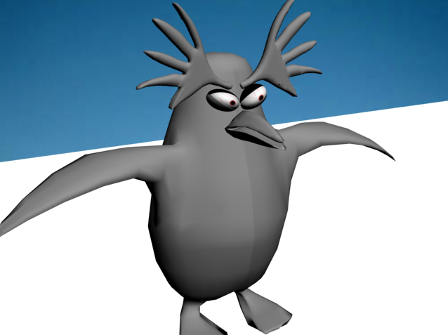
1) b) The character appears onscreen, from the water onto the ice. The character looks around at its surroundings and looks angry before fading to black.
Sound Elements: Big splash when character jumps out of the sea. Character makes frustrated noises and mumbles to himself.
Animation Elements: Splash from the water with the character leaping out of the waves. Animated penguin jumping. Animated frustrated face. Animated beak for the mumbling noises.
Duration:
TBC

2) a) Screen fades from black to show penguins walking in a straight line through the snow. 
Sound Elements: Footsteps in the snow.
Animation Elements: Walking penguins. The production of footsteps in the snow.
Duration:
TBC

2) b) The camera pans round to show the villain character hiding behind a tree. One of the penguins walks past and the villain sticks his foot out on purpose to delibrately trip up the other penguin, which unfortunately falls face down in the snow. The villain finds this hilarious so starts sniggering with delight. Screen transition to next scenerio.
Sound Elements: Sniggering from the villain. The impact of the penguin hitting the snow face down.
Animation Elements: The walking penguin. The hiding villain sticking his foot out. The beak of the penguin as the villain laughs and sniggers evilly.
Duration:
TBC

3) a) Screen shows an igloo with penguins asleep inside, snoring gently. The villain appears onscreen and appears to become annoyed that the penguins are sleeping so content (seeing as he cannot sleep, he is a dead soul).
Sound Elements: Gentle snoring. Footsteps in the snow.
Animation Elements: Z's coming from the igloo to signify the sleeping penguins. The penguin moving onscreen and getting angry.
Duration:
TBC

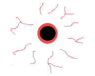
3) b) The camera pans round and zooms in on our villain. This is where we begin to see his true colours. A red mist descends and his eyes glow really bright red. Steam starts to come from where his ears would be and his beak crumples up to show his anger. His eyebrows will also be useful in displaying the emotion. He then grabs some cymbals from somewhere under his rolls of cloth and starts banging them to wake the penguins up.
Sound Elements: Frustrated noises from the penguin. Maybe some dialogue saying "how dare they.." followed by the noise of steam coming from his ears and the banging from the cymbals.
Animation Elements: Red mist descending. Glowing eyes. Steam from the ears (particle emitter). Crumpled beak, which moves to say the short dialogue. Arching eyebrows. Moving arms to reach for the cymbals and to bang them together.
Duration:
TBC

3) c) The light goes on in the igloo and there are angry noises coming from the igloo. In order to not be seen, the villain disappears. A very angry penguin emerges from the igloo ready to confront the villain however as he is nowhere to be seen, the penguin looks around confused and then shrugs. Screen fades to black.
Sound Elements: Angry noises from the penguins. Maybe a noise for when the villain disappears.
Animation Elements: The Z's stop playing. Light comes on in the igloo. Angry penguin walks out of the igloo outside. Angry penguin animated looking around and looking confused. Angry penguin shrugging.
Duration:
TBC

4)  Screen fades from black to display the character onscreen, the camera zooms in and we see more angry expressions before the penguin jumps back into the water. The screen fades to black and credits are played.
Sound Elements: Big splash when character jumps back into the sea. Character makes more frustrated noises and mumbles to himself.
Animation Elements: Splash from the water with the character leaping back into the waves. Animated penguin jumping. Animated frustrated face. Animated beak for mumbling noises.
Duration:
TBC

Additional notes:
After speaking to my teacher, it appears that my storyboard does not fully reflect my evil villain, therefore I will only take one scene of the storyboard and develop it further. The idea I am carrying forward is the scene which involves the sleeping penguins. This is because the snoring acts as the trigger to make the penguin angry. That is when I can display my villain in the best of his glory; narrowing eye movements, moving eyebrows, curled up beak, gestures with his flippers etc.