The following blog post will describe how each of the individual facial features were created. The creation of features was incredibly important because ultimately, they will be what portray my villain's emotions and will accompany gestures.
Eyebrows
The first step was to create a plan for the eyebrows. Due to the amount of detail in them, it meant that it would be difficult to create a base using primitive shapes or by beginning to model straight away with just a few sketches to look at. For accuracy, a guide was created. I used Adobe Illustrator software and used the pen tool to trace over an image of my penguin, saved as an older version of Illustrator file and then imported that into 3D Studio Max. Although I used this method, it is also possible to import the image onto a plane object, use UVW Map to position the eyebrow and then use the line tool to trace. Figure 1 shows the eyebrow traced in Adobe Illustrator whilst figure 2 shows the guide once it has been imported into 3D Studio Max.
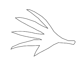 |
| Figure 1: Traced eyebrow guide in Adobe Illustrator |
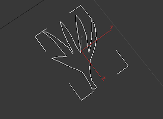 |
| Figure 2: Eyebrow guide imported into 3D Studio Max |
After increasing the size of the eyebrow guide to make it easier to model, I converted the guide to an editable poly and used the Extrude tool to create the eyebrow shape:
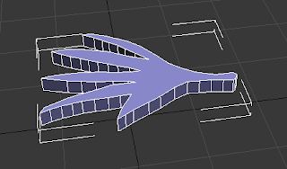 |
| Figure 3: Eyebrow shape after it has been extruded |
In order to create a smooth shape, TurboSmooth would need to be used. However one of the issues I came across was that where the eyebrow was just one large polygon on top and underneath, the smooth modifier would give an undesirable result which was quite messy and unrealistic. In order to find my way around this, I used the cut tool to divide the large polygons up into smaller, more manageable quads. The image below (Figure 4) shows the result after completing this on just one side. As you can see, the issues with the smooth still remain so both sides had to be divided.
 |
| Figure 4: Issues with the TurboSmooth modifier |
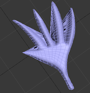
However, once both large polygons were seperated into small quads, there were no more issues as you can see from Fingure 5, displaying the finished eyebrow.
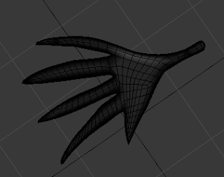 |
| Figure 5: Finished eyebrow, with TurboSmooth turned on |
The eyebrow was then copied (ensuring that it was a copy and not an incidence so that they can be modified independantly of each other) rotated, and then positioned onto the penguin model. The image below (Figure 6) shows the eyebrows in position.
 |
| Figure 6: Eyebrows copied and applied to the penguin model |
Eyes
During week one, eyes were discussed and as a class, we followed a tutorial whereby we created and animated a set of eyes (see Figures 7 and 8). I incorporated these into my design, however I removed the animation element for now. This will be replaced when I begin the animation process of my entire penguin model.
 |
| Figure 7: The makings of my eyes in tutorial 1 week 1 |
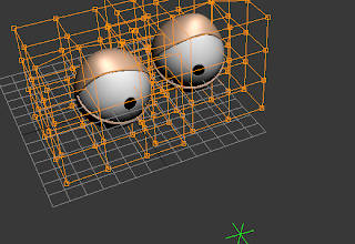 |
| Figure 8: My finished eyes |
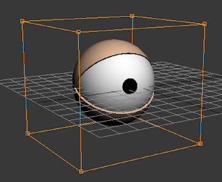
Once the eyes are merged into the penguin model file, they were resized and positioned on the penguin model (see Figure 9).
 |
| Figure 9: Eyes positioned onto the penguin model |
I changed the colour of the eyelids to black to fit in with the penguin theme and I changed the material on the eyeballs as they were not representative of a villain character as they were too plain and cartoon like. I could not find anything appropriate on the internet, therefore I created my own texture using Adobe Photoshop and applied it using the material editor in 3D Studio Max, along with UVW Map to alline it properly. The image below shows the eyeball material (Figure 10).
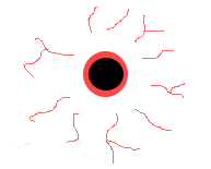 |
| Figure 10: Eyeball material created in Adobe Photoshop |
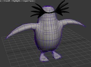
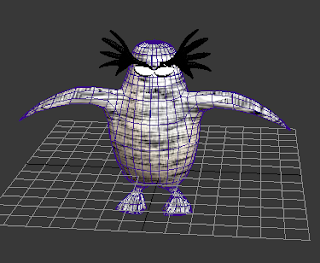
After rotating the eyes as well to make thm look sterner, I took the following screen shot of my penguin in its current state:
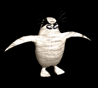 |
| Figure 11: My penguin villain so far with eyes and eyebrows |
NOTE: The material used for the penguin body was only temporary and will be referenced at the end of this blog post.
Beak
The beak of my villain started life as a simple box primitive shape which has been split up into 2x2x2 polygons to make it easier to modify and shape.
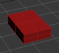 |
| Figure 12: Basic primitive box shape |
After converting the box to an editable poly, I selected vertices and moved them so they formed more of a beak appearance.
 |
| Figure 13: Moving the vertices |
The middle vertices were pulled up to form the part of the beak that sits highest up on the penguin's face. The lower part of the beak is pulled down to make it easier to differentiate between the top of the beak and the bottom.
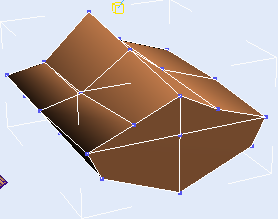 |
| Figure 14: The beak is beginning to take more shape |
When rearranging vertices, it can be easier to view the model in wireframe mode. In order to give the beak shape, the vertex in the middle of the image shown above (see Figure 15) has been pulled out and the surrounding vertices adjusted slightly.
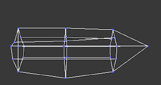 |
| Figure 15: The beak in wireframe view |
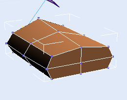
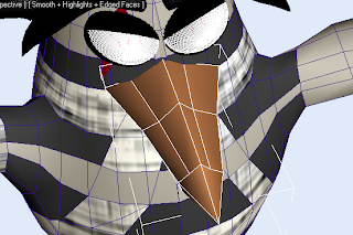
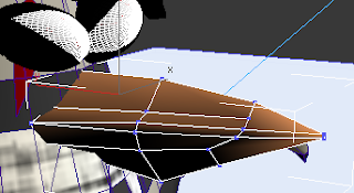
After alligning the basis of the penguins beak, it was moved into position on the penguin model and the resize tool was used to give the beak more definition, starting with the middle vertices (See Figure 16) and ending with the end vertices (See Figure 17).
 |
| Figure 16: Formation of beak shape |
 |
| Figure 17: Beak shape accomplished |
Next, the chamfer tool was used to add more polygons on the beak.
 |
| Figure 18: Using the chamfer tool to provide more polygons |
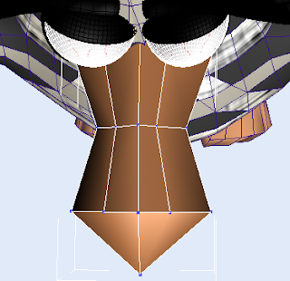
The inset tool was used and the new polygons have then been resized to make the beak "open". It also gives the beak a hinge so when I come to animate the penguin's beak, it can be opened and shut. The vertices can also be moved around so if I wanted to have my penguin read a monologue, it can be lip synced fairly easily.
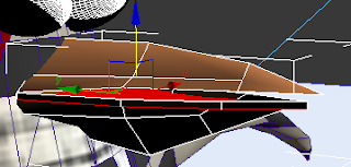 |
| Figure 19: Resizing the new polygons to create a slightly open beak |
The final touch was to rotate the beak slightly to give it a more curved and dangerous position. The finished beak is displayed in Figure 20.
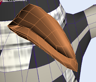 |
| Figure 20: Finished beak structure |


No comments:
Post a Comment